


 HOME
HOMEPressure Control Strategies for High-Pressure Pipe Testing Systems
20 July 2026
Written by: Marley Machinery Engineering Team
Pressure control determines the reliability of every hydrostatic pipe test. In high-pressure pipe testing systems, achieving the target pressure is only one objective; maintaining pressure stability, minimizing hydraulic disturbance, and ensuring repeatable pressure behavior are equally critical. The optimal control strategy depends on pipe dimensions, test pressure, hydraulic circuit characteristics, production throughput, and inspection requirements. Whether integrated into a hydro testing machine for pipe or a complete pipe hydro testing equipment line, pressure control should be designed to produce consistent pressure curves rather than simply reaching the specified pressure as quickly as possible.
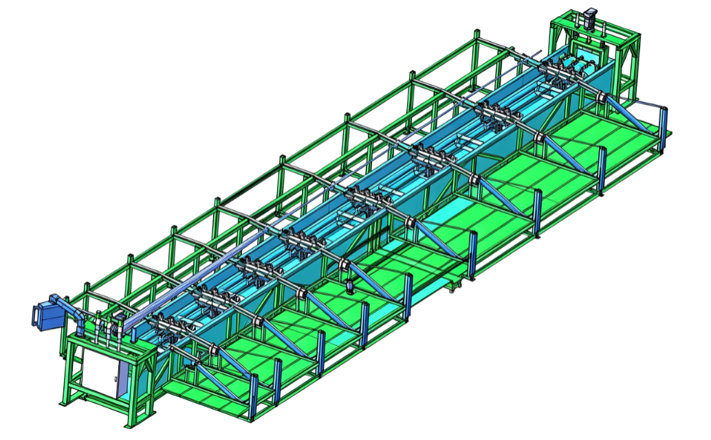
Engineering Objectives: Designing Pressure Control Around Process Stability
Pressure control is often evaluated by one simple question:
Can the system reach the required pressure?
From an engineering standpoint, this is the wrong question.
The more important question is:
Can the system reach the required pressure repeatedly, predictably, and without introducing unnecessary hydraulic instability?
In a production pipe mill, the pressure control system is expected to perform thousands of testing cycles every week. During that time, pipe diameter, wall thickness, steel grade, and customer specifications may change continuously. A pressure control strategy that performs well under one operating condition may become unstable under another if the hydraulic system has not been designed with sufficient flexibility.
For this reason, experienced engineers evaluate pressure control according to four primary objectives.
|
Engineering Objective |
Why It Matters |
Engineering Priority |
|
Pressure Repeatability |
Ensures identical testing conditions across production batches |
More important than achieving the shortest cycle time |
|
Hydraulic Stability |
Prevents oscillation, overshoot, and pressure fluctuations |
Improves measurement reliability and equipment life |
|
Process Adaptability |
Maintains stable control for different pipe specifications |
Reduces manual parameter adjustments |
|
Energy Efficiency |
Minimizes unnecessary hydraulic loading |
Improves long-term operating efficiency |
Unlike laboratory pressure systems, production equipment must continuously balance testing accuracy with manufacturing efficiency. Increasing pressure too aggressively may shorten the testing cycle, but it also increases hydraulic shock, accelerates seal wear, and makes pressure stabilization more difficult. Conversely, an excessively conservative control strategy improves stability but reduces line throughput.
The objective is therefore not to maximize pressure response speed, but to maintain stable and repeatable pressure behavior across the entire operating range.
Engineering Insight
In modern pipe hydro testing equipment, repeatability is generally a more valuable performance indicator than maximum pressure capability. A pressure system that produces nearly identical pressure curves every cycle is easier to validate, maintain, and optimize over time.
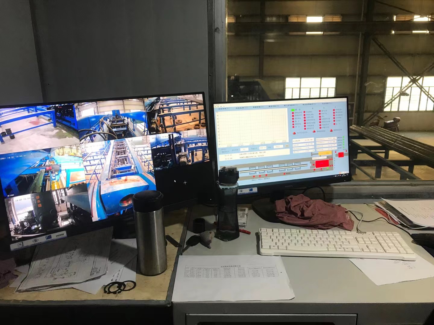
Engineering Principles: Pressure Is the Result—System Dynamics Determine the Outcome
Pressure is frequently treated as the primary process variable during hydrostatic testing. In reality, pressure is only the visible result of multiple hydraulic and mechanical interactions occurring simultaneously.
As the hydraulic circuit begins to build pressure, the system responds as a dynamic structure rather than a collection of independent components.
Several events occur within seconds:
- The pipe expands elastically under internal loading.
- Water stores elastic energy within the hydraulic circuit.
- Control valves continuously adjust flow to match the pressure demand.
- Residual air compresses rapidly if venting is incomplete.
- Pressure sensors measure a continuously changing hydraulic condition rather than a static value.
These events explain why two hydro testing machines for pipe equipped with identical pumps can produce noticeably different pressure characteristics.
The difference often lies not in pump capacity, but in the overall dynamic response of the hydraulic system.
Engineers therefore focus on controlling pressure development, not simply pressure generation.
Three engineering principles dominate pressure control performance.
Hydraulic Response Must Be Predictable
Every pressure control system has a characteristic response.
If the hydraulic circuit reacts too aggressively, pressure overshoot and oscillation become difficult to suppress. If the response is too slow, production efficiency decreases and pressure regulation becomes sluggish during transient conditions.
An effective pressure control strategy seeks a critically damped response, allowing pressure to approach the target smoothly without excessive correction.
This balance is achieved through the combined design of hydraulic components, control algorithms, accumulator sizing, and valve characteristics—not by adjusting a single parameter.
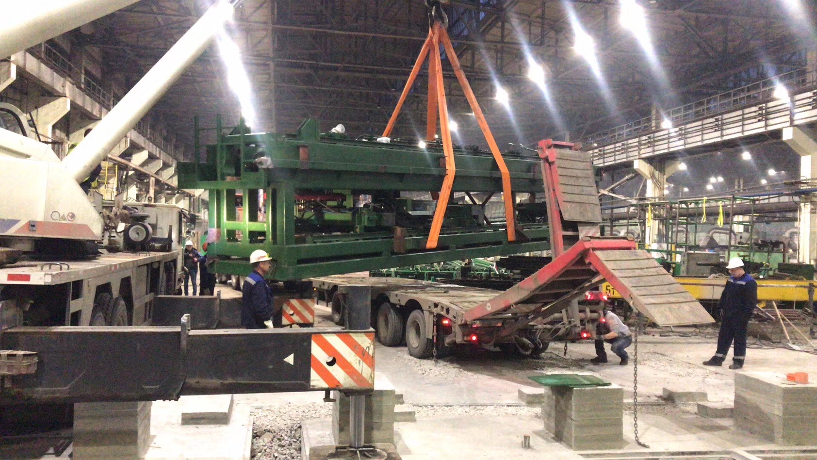
Stable Pressure Curves Are More Valuable Than Peak Pressure
Many acceptance specifications define only the target pressure and holding duration.
However, experienced commissioning engineers evaluate the complete pressure curve before examining the final pressure value.
A smooth pressure curve generally indicates:
- Stable hydraulic regulation
- Proper valve response
- Effective air removal
- Correct controller tuning
- Consistent sealing conditions
By comparison, repeated oscillations, irregular corrections, or pressure overshoot usually indicate that the control strategy requires adjustment long before testing accuracy is affected.
For this reason, pressure curve analysis has become one of the most valuable diagnostic tools during equipment commissioning and production optimization.
Engineering Insight
A pressure curve contains significantly more engineering information than a single pressure reading. It reveals how the hydraulic system behaves—not merely the pressure it eventually reaches.
Control Accuracy Depends on System Coordination
Pressure control should never be viewed as the responsibility of the hydraulic power unit alone.
Accurate regulation depends on coordinated interaction between:
- Hydraulic power generation
- Proportional or servo valves
- Pressure transmitters
- PLC control logic
- Mechanical sealing systems
- Data acquisition hardware
Improving only one subsystem rarely improves overall control performance.
For example, installing a higher-accuracy pressure transmitter cannot eliminate oscillation caused by poorly tuned proportional valves. Likewise, increasing pump flow cannot compensate for delayed control signals or unstable hydraulic stiffness.
The performance of the entire pressure control system is therefore determined by the weakest interaction between its subsystems rather than by the highest specification of any individual component.
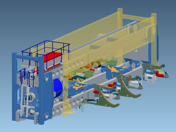
System Architecture: Building a Stable Pressure Control System
In a high-pressure pipe hydro testing machine, pressure regulation should be designed as a closed control loop in which every subsystem continuously exchanges information throughout the testing cycle.
Production Control System
│
▼
PLC / Industrial PC
│
┌─────────────────────┼─────────────────────┐
▼ ▼ ▼
Pressure Transmitter Motion Controller Data Acquisition
│ │ │
└──────────────┬──────┴──────────────┬──────┘
▼ ▼
Proportional / Servo Valve Hydraulic Power Unit
│
▼
Pressure Control Circuit
│
▼
End Sealing & Pipe Under Test
Unlike conventional hydraulic equipment, every component within this architecture contributes directly to pressure quality.
The pressure transmitter supplies real-time feedback.
The PLC calculates the required correction.
The proportional or servo valve regulates hydraulic flow.
The hydraulic power unit provides the available energy.
The sealing system maintains a stable pressure boundary.
Failure or delay in any one of these elements immediately affects pressure stability, even when every other subsystem is operating correctly.
This explains why experienced engineers diagnose pressure instability by analyzing the complete control loop rather than replacing individual hydraulic components.
Critical Engineering Parameters
Before selecting a pressure control strategy, engineers normally evaluate several operating parameters that collectively determine control performance.
|
Engineering Parameter |
Why It Matters |
Typical Industrial Value |
Engineering Notes |
|
Pressure Ramp Rate |
Controls transient hydraulic response |
Multi-stage programmable ramp |
Excessive ramp rates increase overshoot and seal loading. |
|
Pressure Stability |
Determines inspection repeatability |
Typically maintained within a narrow process tolerance |
Excessive ramp rates increase overshoot and seal loading. |
|
Control Response Time |
Affects pressure correction speed |
Millisecond-level PLC response with fast valve feedback |
Fast response without proper tuning may create oscillation. |
|
Sampling Frequency |
Determines pressure curve resolution |
High-frequency continuous acquisition |
Low sampling rates may hide transient instability. |
|
Hydraulic Stiffness |
Influences pressure consistency |
Maximized by minimizing trapped air and system compliance |
Often overlooked during commissioning despite its significant impact. |
The parameters above should never be optimized independently. Increasing response speed, for example, may reduce pressure settling time but also increase control instability if valve dynamics, hydraulic stiffness, and controller tuning are not adjusted simultaneously.
Selecting the Right Control Architecture: There Is No Universal Solution
One of the most common misconceptions in hydrostatic testing is that a single pressure control strategy can satisfy every production requirement. In reality, the optimal solution depends on how the hydraulic system responds under different operating conditions.
A production line manufacturing API line pipe in only two diameters has fundamentally different control requirements from a mill processing dozens of pipe specifications every shift. Likewise, testing heavy-wall seamless pipe demands a different pressure response than testing thin-wall welded pipe, even when the specified test pressure is identical.
For this reason, experienced engineers select a control architecture based on process characteristics, not simply on the maximum pressure rating of the equipment.
The first engineering decision is whether pressure regulation should prioritize response speed, pressure repeatability, or operational flexibility. Improving one objective usually requires compromise in another.
|
Control Strategy |
Engineering Advantage |
Engineering Limitation |
Typical Application |
|
Open-loop Pressure Control |
Simple architecture and low implementation cost |
Unable to compensate for process disturbances |
Small-capacity or manually operated testing systems |
|
Closed-loop PID Control |
Stable pressure regulation with automatic correction |
Requires proper tuning for different production conditions |
Most modern pipe hydro testing machines |
|
Servo-Hydraulic Control |
Excellent repeatability and dynamic response |
Higher investment and commissioning complexity |
High-pressure alloy pipe and premium OCTG production |
|
Adaptive Pressure Control |
Automatically adjusts control parameters during production |
Greater software complexity and higher integration requirements |
Flexible manufacturing systems with frequent product changes |
Selecting a more sophisticated control system does not automatically improve testing performance. A poorly tuned servo system often performs worse than a properly configured proportional hydraulic system.
Engineering Insight
Control architecture should always match production variability. Overengineering the control system increases commissioning complexity without necessarily improving inspection reliability.
Pressure Dynamics: Why Pressure Overshoot Is More Serious Than Slow Pressurization
Engineers often focus on reducing testing cycle time by increasing the pressure ramp rate. While this approach can shorten individual test cycles, it also changes the dynamic behavior of the hydraulic circuit.
As pressure rises rapidly, stored hydraulic energy increases throughout the system. If the controller cannot reduce hydraulic flow quickly enough near the target pressure, the system continues to build pressure beyond the specified value.
This phenomenon, known as pressure overshoot, creates several engineering problems simultaneously:
- Higher mechanical loading on the sealing assembly.
- Increased stress on hydraulic piping and valves.
- Longer stabilization time before evaluation.
- Reduced pressure repeatability between consecutive tests.
- Greater tuning sensitivity within the control algorithm.
Contrary to common assumptions, pressure overshoot is not always caused by excessive pump capacity. In many installations it results from delayed valve response, insufficient controller tuning, excessive hydraulic compliance, or signal latency between sensors and the PLC.
The engineering objective is therefore not to eliminate overshoot by slowing every pressure ramp. Instead, the controller should reduce hydraulic energy progressively as the target pressure approaches.
A well-designed pressure curve typically exhibits three distinct characteristics:
- Smooth acceleration during the initial pressure ramp.
- Controlled deceleration before reaching target pressure.
- Minimal correction after the target pressure is achieved.
These characteristics indicate that the hydraulic system is regulating pressure rather than continuously correcting its own instability.
Why PID Tuning Cannot Be Standardized
One of the most frequent questions during commissioning is whether a single PID parameter set can be applied across different production lines.
In practice, the answer is almost always no.
PID performance depends on the dynamic characteristics of the complete hydraulic system, including:
- Pipe volume
- Hydraulic oil temperature
- Pump response
- Valve characteristics
- Accumulator sizing
- Pressure transmitter response
- Hydraulic piping length
Changing any of these variables alters the behavior of the control loop.
For example, increasing the tested pipe diameter increases the internal water volume, reducing the pressure response speed. A PID configuration that performs well on a small-diameter production line may become unstable when applied to larger products.
Similarly, hydraulic oil temperature changes the viscosity of the fluid, directly affecting valve response and actuator behavior. During continuous production, control performance may gradually change even though no hardware has been replaced.
Experienced commissioning engineers therefore tune PID parameters according to the operating characteristics of the production line rather than attempting to establish universal settings.
Engineering Insight
Stable PID tuning is achieved by understanding hydraulic dynamics, not by repeatedly adjusting controller gains until oscillation disappears.
Process Analysis: Pressure Quality Is Built Step by Step
Reliable pressure control is established throughout the testing cycle rather than during the holding stage alone.
Each stage prepares the conditions required for the next.
Water Filling
│
▼
Air Removal
│
▼
Low-Pressure Seal Verification
│
▼
Controlled Pressure Ramp
│
▼
Pressure Stabilization
│
▼
Pressure Holding
│
▼
Controlled Pressure Release
The engineering purpose of each stage differs significantly.
|
Process Stage |
Why It Matters |
Engineering Risk if Poorly Controlled |
|
Water Filling |
Establishes consistent hydraulic conditions |
Residual air reduces system stiffness and affects repeatability |
|
Air Removal |
Eliminates compressible volume before pressurization |
Pressure oscillation and delayed stabilization |
|
Low-Pressure Seal Verification |
Confirms sealing integrity before full loading |
False leakage and unnecessary seal damage |
|
Controlled Pressure Ramp |
Builds pressure while limiting hydraulic shock |
Overshoot, valve instability, and excessive mechanical stress |
|
Pressure Stabilization |
Allows hydraulic equilibrium before evaluation |
False interpretation of natural pressure variation |
|
Pressure Holding |
Performs leak evaluation under stable conditions |
Incorrect acceptance or rejection decisions |
|
Controlled Pressure Release |
Removes stored hydraulic energy safely |
Mechanical shock and accelerated component wear |
An experienced engineer rarely evaluates one stage in isolation.
For example, unstable pressure during the holding period may originate from incomplete air removal several minutes earlier. Likewise, repeated overshoot may result from an inappropriate pressure ramp rather than poor PID tuning.
Understanding these relationships allows engineers to identify root causes instead of treating symptoms.
Engineering Best Practices
Pressure control should always be optimized as a complete process rather than as a collection of independent settings.
The following practices have consistently improved pressure repeatability in high-pressure pipe testing systems across different production environments:
- Develop pressure using programmable multi-stage ramps instead of a constant pressure increase rate.
- Begin leak evaluation only after the pressure change rate has stabilized rather than after a fixed waiting time.
- Review complete pressure curves during commissioning instead of relying solely on maximum pressure values.
- Tune control parameters under normal production conditions rather than during unloaded equipment testing.
- Verify hydraulic stiffness whenever pressure stability deteriorates before replacing sensors or valves.
- Record pressure trend data for every production cycle to identify gradual changes in system performance before they become quality issues.
Engineering Insight
The most effective pressure control strategy is not the one that reaches target pressure first. It is the one that delivers the same pressure behavior for the first pipe, the hundredth pipe, and the thousandth pipe under normal production conditions.
Why Stable Hardware Can Still Produce Unstable Pressure
Pressure instability is not always caused by hardware failure. In many production facilities, every hydraulic component operates within specification, yet the pressure control system still produces inconsistent results.
The reason is that pressure regulation depends on the interaction between hydraulic dynamics, mechanical response, control algorithms, and operating conditions. Small deviations in several subsystems often combine into a significant reduction in control performance.
Experienced engineers therefore investigate the complete control loop before replacing individual components.
|
Observed Condition |
Most Likely Engineering Cause |
Recommended Engineering Action |
|
Pressure overshoots the target repeatedly |
Pressure ramp too aggressive or controller response too slow |
Reduce ramp rate near target pressure and verify valve response characteristics |
|
Pressure oscillates during holding |
Improper PID tuning, trapped air, or low hydraulic stiffness |
Review pressure trend, inspect venting system, and evaluate hydraulic compliance |
|
Stabilization time becomes progressively longer |
Hydraulic oil temperature variation, accumulator condition, or residual air |
Verify oil temperature, accumulator pre-charge, and air removal efficiency |
|
Pressure curves vary between identical pipes |
Process inconsistency rather than product variation |
Compare filling sequence, stabilization criteria, and control parameters |
|
Pressure remains stable but external leakage occurs |
End seal displacement or insufficient sealing force |
Inspect seal alignment before adjusting pressure control parameters |
One principle should guide every troubleshooting activity:
Investigate the process before replacing hardware.
In many cases, the control strategy is functioning exactly as designed. The instability originates from changing operating conditions that have shifted the hydraulic response outside the controller's optimal range.
Engineering Insight
Pressure controllers do not create stability—they respond to system behavior. If the hydraulic process becomes unstable, even the most advanced controller can only compensate within its design limits.
Applicable Standards
International standards specify the required testing conditions but generally do not prescribe how pressure should be controlled. Developing a reliable pressure control strategy therefore requires combining code compliance with sound hydraulic engineering practice.
|
Standard |
Primary Focus |
Relevance to Pressure Control |
|
API 5L |
Hydrostatic testing requirements for line pipe |
Defines required test pressure and acceptance requirements for pipeline products. |
|
API 5CT |
Casing and tubing |
Establishes testing requirements for OCTG products operating under demanding service conditions. |
|
ASTM A530/A530M |
General requirements for steel pipe |
Specifies common hydrostatic testing and inspection requirements. |
|
ASTM A999/A999M |
Stainless steel pipe |
Covers pressure testing requirements applicable to stainless steel products. |
|
ISO 3183 |
Line pipe |
Defines technical delivery conditions for pipeline manufacturing. |
|
ISO 10893 Series |
Non-destructive testing of steel tubes |
Complements hydrostatic testing by integrating additional inspection methods. |
|
ASME B31.3 |
Process piping |
Provides pressure testing requirements for installed piping systems and serves as a valuable engineering reference for pressure control philosophy. |
Meeting the minimum requirements of a standard does not automatically guarantee stable pressure control. Repeatability, pressure curve quality, and measurement integrity remain engineering responsibilities that extend beyond code compliance.
Future Pressure Control Technologies
The next generation of pipe hydro testing equipment is expected to improve pressure quality through better process intelligence rather than simply increasing hydraulic capacity.
Several engineering developments are already influencing modern pressure control system design.
Adaptive Pressure Regulation
Instead of using one fixed control parameter set, adaptive controllers continuously modify pressure response according to pipe dimensions, hydraulic conditions, and system behavior. This reduces manual retuning when production schedules change.
High-Speed Pressure Curve Analysis
Rather than evaluating only the final pressure value, advanced systems analyze the complete pressure profile to identify oscillation, overshoot, abnormal stabilization, and other process deviations before they influence inspection results.
Integrated Process Diagnostics
Future hydro testing machines for pipe will increasingly compare current pressure curves with historical production data. Deviations from established process patterns can be detected automatically, allowing maintenance teams to investigate developing hydraulic problems before quality is affected.
These developments represent an evolution in control philosophy.
The objective is no longer simply to regulate pressure.
The objective is to continuously evaluate the quality of the pressure control process itself.
Selecting the appropriate pressure control strategy requires understanding hydraulic system dynamics rather than choosing the fastest pressure response or the most sophisticated controller. Stable pressure regulation is achieved when hydraulic hardware, valve characteristics, controller tuning, measurement accuracy, and process sequencing operate as a coordinated system.
For modern hydro testing machine for pipe, the most effective pressure control strategy is one that consistently produces repeatable pressure curves under changing production conditions. Engineers who prioritize process stability over peak performance typically achieve higher inspection reliability, lower maintenance requirements, and more consistent compliance with international testing standards.


