


 HOME
HOMEThe Complete Guide to Hydro Testing Machine For Pipe
17 July 2026
Written by: Marley Machinery Engineering Team
A modern hydro testing machine for pipe should be designed as a pressure control system rather than simply a pressure generation system. Reliable hydrostatic testing depends on maintaining hydraulic stability throughout the entire testing cycle—from filling and air removal to pressure stabilization, holding, measurement, and controlled depressurization. In industrial pipe production, repeatable test results are achieved by controlling system dynamics, minimizing measurement uncertainty, and synchronizing hydraulic, mechanical, and automation functions. This guide explains the engineering principles, design decisions, and practical considerations that determine testing reliability in modern pipe manufacturing facilities.
Engineering Objectives: Pressure Verification Is Only the Final Result
Hydrostatic testing is often described as a method of verifying pipe integrity. From an engineering perspective, however, verification is only the outcome. The real challenge lies in creating a testing process that produces consistent, repeatable, and traceable results regardless of production volume or product variation.
For a pipe mill running continuously, thousands of hydrostatic tests may be completed during a single production shift. Under these conditions, the objective is no longer to determine whether one pipe passes or fails. Instead, engineers must ensure that every pipe is evaluated under nearly identical testing conditions.
This distinction fundamentally changes how a hydro testing machine should be designed.
A machine capable of generating extremely high pressure offers little value if pressure stability varies from one cycle to the next. Likewise, highly accurate pressure sensors cannot compensate for unstable hydraulic behavior, poor sealing alignment, or inconsistent automation sequences.
For this reason, experienced equipment designers evaluate a hydro testing system using four engineering objectives rather than a single pressure specification.
|
Engineering Objective |
Why It Matters |
Engineering Consideration |
|
Repeatability |
Ensures every pipe is tested under comparable conditions |
Hydraulic stability is more important than peak pressure. |
|
Measurement Integrity |
Prevents false acceptance or unnecessary rejection |
Sensor placement, calibration, and signal filtering must work together. |
|
Production Efficiency |
Maintains throughput without sacrificing test quality |
Pressure profile optimization is generally more effective than simply increasing pump capacity. |
|
Equipment Reliability |
Reduces maintenance cost and unplanned downtime |
Mechanical loading should remain predictable throughout every pressure cycle. |
The most reliable hydro testing machines are not necessarily those with the highest pressure rating. They are the systems that produce nearly identical pressure curves across thousands of consecutive testing cycles.
Engineering Principles: Why Pressure Stability Determines Testing Accuracy
Many discussions about hydrostatic testing focus on the specified test pressure. In practice, experienced engineers are often more interested in how the system reaches that pressure than the pressure value itself.
The reason is straightforward: pressure is only one observable result of a much larger hydraulic process.
During pressurization, several physical phenomena occur simultaneously. The pipe expands elastically, the hydraulic circuit stores energy, valves adjust continuously to changing flow conditions, and any remaining trapped air compresses rapidly. These events occur within seconds, yet together they determine whether the measured pressure accurately represents the condition of the pipe.
A stable pressure reading therefore does not simply indicate that the pump has reached its target. It indicates that the entire hydraulic system has approached equilibrium.
This is why modern hydro testing machines increasingly rely on closed-loop pressure regulation instead of open-loop hydraulic control. Rather than commanding the pump to deliver a fixed output, the control system continuously compares actual pressure with the target value and makes small corrections throughout the testing cycle. The objective is not faster pressurization, but smoother and more predictable pressure behavior.
One common misconception is that increasing pump capacity automatically improves production efficiency. While a larger pump can shorten filling time, it also increases the likelihood of pressure overshoot, hydraulic shock, and unnecessary mechanical loading if the control strategy is not adapted accordingly. In many production lines, a well-tuned control algorithm delivers greater improvements in cycle consistency than a higher-capacity hydraulic power unit.
Engineering Insight
Engineers troubleshooting unstable test results often replace pressure sensors first. More frequently, however, the underlying cause is unstable hydraulic behavior rather than inadequate measurement accuracy.
System Architecture: Designing an Integrated Testing System
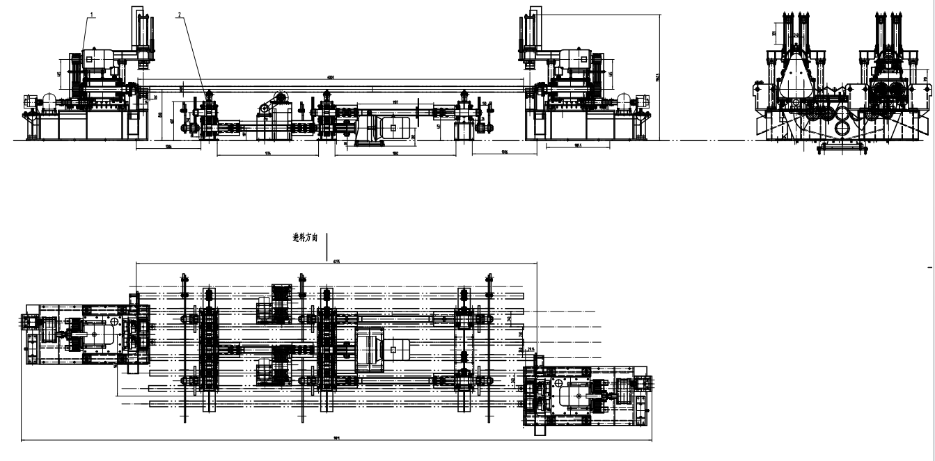
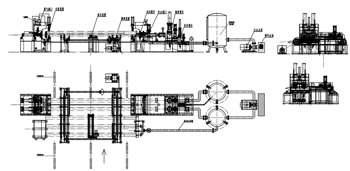
A hydro testing machine should never be viewed as a hydraulic unit with several auxiliary components attached. It is an integrated engineering system in which every subsystem influences testing accuracy.
Production Management System
│
▼
PLC & HMI Controller
│
┌────────────────────┼────────────────────┐
▼ ▼ ▼
Hydraulic Power Motion Control Data Acquisition
│ │ │
▼ ▼ ▼
Pressure Control Pipe Positioning Pressure Monitoring
└────────────────────┼────────────────────┘
▼
End Sealing Assembly
▼
Pipe Under Test
The architecture above reflects a fundamental design philosophy: pressure generation, positioning, sealing, measurement, and data recording are interdependent functions rather than independent systems.
Consider the sealing sequence as an example. The hydraulic cylinders may achieve their commanded position within milliseconds, but pressure testing should not begin until the control system confirms that the sealing force has stabilized and all process interlocks have been satisfied. Initiating pressurization too early can create minor seal movement during pressure build-up, producing pressure fluctuations that resemble leakage even when the pipe itself is completely sound.
Similarly, pressure data should not be recorded immediately after the target pressure is reached. The hydraulic circuit requires a brief stabilization period to allow transient responses to decay before meaningful evaluation can begin.
These timing relationships explain why two machines equipped with similar hydraulic hardware may deliver significantly different testing performance. The difference often lies not in the components themselves, but in how those components are coordinated by the control system.
Engineering Parameter Framework
Before discussing pressure control strategies in detail, engineers typically evaluate several parameters that collectively determine testing performance.
|
Parameter |
Why It Matters |
Typical Engineering Practice |
|
Pressure Ramp Profile |
Influences hydraulic stability and mechanical loading |
Multi-stage closed-loop pressure ramp |
|
Stabilization Time |
Allows transient hydraulic effects to dissipate |
Determined by system response rather than a fixed timer |
|
Pressure Measurement |
Forms the basis of pass/fail decisions |
High-accuracy transmitters with periodic verification |
|
Hydraulic Stiffness |
Affects repeatability of every testing cycle |
Minimize trapped air and unnecessary system compliance |
|
Sealing Force |
Prevents leakage without excessive mechanical stress |
Matched to pipe geometry and operating pressure |
|
Data Sampling Rate |
Determines diagnostic capability |
Continuous recording during pressurization and holding |
Pressure Control Strategy: Why Stable Pressure Matters More Than Fast Pressurization
The pressure ramp is the most dynamic stage of the hydrostatic testing cycle and the point at which many testing inaccuracies originate. While the target pressure is predetermined by the applicable product specification, the path taken to reach that pressure is entirely an engineering decision.
In modern pipe mills, pressure is rarely increased at a constant rate from start to finish. Instead, the process is divided into multiple control stages because the hydraulic system behaves differently as pressure rises.
A typical pressure control sequence includes:
Water Filling
│
▼
Low-Pressure Seal Verification
│
▼
Controlled Pressure Ramp
│
▼
Pressure Stabilization
│
▼
Pressure Holding
│
▼
Controlled Depressurization

Each stage serves a different engineering purpose.
During low-pressure verification, the objective is to confirm that the sealing system is correctly positioned before significant internal forces develop. Detecting a sealing problem at this stage prevents unnecessary loading of the pipe and avoids exposing hydraulic components to excessive stress.
The controlled pressure ramp then increases pressure at a rate that the hydraulic circuit can respond to predictably. Excessively aggressive pressurization often produces pressure overshoot, valve oscillation, and unnecessary loading on seals and piping. Slowing the ramp indiscriminately is not the solution either, as longer cycles reduce line productivity without necessarily improving measurement quality.
The preferred strategy is a variable pressure ramp that adapts to system response rather than maintaining a fixed pressure increase throughout the cycle.
Engineering Insight
A well-designed pressure ramp minimizes hydraulic instability rather than minimizing cycle time. Stable pressure development produces more reliable inspection results than rapid pressurization followed by corrective adjustments.
Why Pressure Stabilization Cannot Be Replaced by a Fixed Timer
Many production specifications define a minimum holding time but provide little guidance on stabilization.
In practice, stabilization is not simply a waiting period. It is the time required for the hydraulic system to reach equilibrium after pressurization.
Several transient effects continue after the target pressure has been reached:
- Elastic expansion of the pipe wall
- Compression of any remaining entrapped air
- Pressure redistribution within manifolds and hoses
- Valve position correction by the control system
- Dissipation of pressure waves throughout the circuit
If leak evaluation begins before these effects have settled, natural pressure changes may be interpreted as leakage.
For this reason, advanced testing systems increasingly determine stabilization using pressure trend analysis rather than a fixed countdown. When the pressure change rate falls below a predefined threshold, the system automatically transitions to the holding stage.
This approach improves repeatability across different pipe sizes and testing pressures because stabilization is determined by actual hydraulic behavior instead of an arbitrary time value.
Hydraulic Design Trade-Offs
Selecting hydraulic components is not simply a matter of choosing higher capacity equipment. Every design decision involves compromises between response speed, stability, efficiency, maintenance requirements, and operating cost.
|
Design Choice |
Engineering Advantage |
Engineering Limitation |
Recommended Application |
|
High-flow hydraulic pump |
Shorter filling time |
Higher risk of pressure overshoot if poorly controlled |
High-volume production lines |
|
Variable-displacement pump |
Improved energy efficiency under varying loads |
Greater control complexity |
Mixed-size pipe production |
|
Fixed-displacement pump |
Simple and robust |
Reduced operating flexibility |
Dedicated production lines with stable specifications |
|
Servo-controlled pressure regulation |
Excellent pressure repeatability |
Higher investment and maintenance requirements |
High-value alloy and OCTG production |
|
Proportional valve control |
Good balance between cost and performance |
Requires careful tuning |
Most industrial pipe mills |
A mill producing multiple pipe diameters each day requires flexibility and adaptive control. A dedicated production line manufacturing a single specification often benefits more from simplicity and reliability than from sophisticated control hardware.
Engineering Insight
Hydraulic systems should be sized for stable operation across the expected production range—not for the highest pressure the equipment may encounter only occasionally.
Why Air Removal Is a Measurement Problem Rather Than a Filling Problem
Air removal is frequently considered part of the filling process. From an engineering standpoint, it is more accurately viewed as a measurement issue.
Water is only slightly compressible under hydrostatic testing conditions, whereas air is highly compressible. Even a relatively small volume of trapped air changes the effective stiffness of the hydraulic system.
The consequences extend well beyond slower pressure build-up.
Residual air can:
- Delay pressure stabilization.
- Increase pressure oscillation.
- Reduce leak detection sensitivity.
- Produce inconsistent pressure curves between otherwise identical pipes.
- Increase the likelihood of false pressure decay during the holding stage.
These effects become increasingly significant as the internal volume of the test specimen increases. Large-diameter pipes require greater attention to venting strategy because a small percentage of trapped air represents a much larger absolute volume.
Rather than maximizing filling speed, experienced engineers optimize vent locations, filling direction, and vent timing to remove air before pressurization begins.
Process Analysis: Where Testing Accuracy Is Actually Determined
Although hydrostatic testing is often judged by the holding stage, the quality of the final result is largely established much earlier in the cycle.
|
Process Stage |
Primary Engineering Objective |
Common Failure Mode |
Engineering Priority |
|
Water Filling |
Remove air while ensuring continuous flow |
Residual air pockets |
Hydraulic consistency |
|
Seal Verification |
Confirm sealing integrity before loading |
Misalignment or insufficient contact |
Prevent false leakage |
|
Pressure Ramp |
Build pressure without hydraulic shock |
Overshoot and oscillation |
Stable pressure development |
|
Stabilization |
Reach hydraulic equilibrium |
Premature data acquisition |
Measurement repeatability |
|
Pressure Holding |
Evaluate pressure under stable conditions |
Misinterpretation of pressure decay |
Reliable acceptance decision |
|
Controlled Depressurization |
Release stored hydraulic energy safely |
Pressure shock during unloading |
Equipment protection |
The engineering objective changes at every stage of the cycle. Treating the entire process as a single pressurization event often masks the true source of testing problems.
For example, pressure instability observed during the holding stage may actually originate from incomplete air removal during filling or from excessive pressure overshoot during the ramp phase. Corrective action therefore requires understanding how each process stage influences the next rather than optimizing them independently.
Engineering Insight
Most repeatability problems do not originate where they become visible. Engineers who analyze the complete pressure cycle instead of focusing only on the holding stage identify root causes more quickly and avoid unnecessary adjustments to otherwise stable equipment.
Failure Analysis: When Pressure Loss Does Not Always Indicate Pipe Leakage
A pressure drop during hydrostatic testing does not necessarily indicate a defective pipe. In many production lines, the apparent loss of pressure originates from the testing system rather than the test specimen itself.
Effective troubleshooting begins by distinguishing product-related defects from process-related instability. Replacing seals, sensors, or hydraulic components without identifying the actual source of pressure variation often increases maintenance costs while failing to improve testing reliability.
|
Observed Condition |
Possible Cause |
Engineering Verification |
|
Slow pressure decay |
Internal leakage or hydraulic leakage |
Isolate the hydraulic circuit and repeat the pressure test without the pipe. |
|
Sudden pressure loss |
Seal displacement or valve instability |
Verify seal alignment and review the pressure curve during the ramp stage. |
|
Pressure oscillation |
Trapped air, improper PID tuning, or accumulator pre-charge deviation |
Analyze the complete pressure curve rather than the final pressure value. |
|
Different results on identical pipes |
Process variation |
Compare stabilization time, filling sequence, and sealing conditions between cycles. |
|
Water leakage with stable pressure |
External seal leakage |
Inspect the end sealing assembly before rejecting the pipe. |
Engineering Insight
When several consecutive pipes fail under similar conditions, engineers should first investigate the testing system. Multiple process-related failures are generally more likely than simultaneous defects in successive pipes.
Applicable Standards
International standards define minimum testing requirements, but they do not specify how a hydro testing machine should be engineered. Reliable testing performance depends on translating these requirements into stable hydraulic design, accurate pressure measurement, and repeatable process control.
|
Standard |
Primary Focus |
Engineering Significance |
|
API 5L |
Hydrostatic testing requirements for line pipe |
Establishes pressure testing requirements for pipeline steel. |
|
API 5CT |
Casing and tubing |
Defines hydrostatic testing requirements for OCTG products. |
|
ASTM A530/A530M |
General requirements for steel pipe |
Provides common testing and inspection requirements. |
|
ASTM A999/A999M |
Stainless steel pipe |
Covers inspection and hydrostatic testing requirements for stainless products. |
|
ISO 10893 Series |
Non-destructive testing of steel tubes |
Complements hydrostatic testing with additional inspection methods. |
|
ISO 3183 |
Line pipe |
Specifies technical delivery requirements for pipeline applications. |
|
ASME B31.3 |
Process piping |
Defines pressure testing requirements after piping installation rather than during manufacturing. |
Customer specifications should always be reviewed together with applicable standards, as project requirements frequently exceed the minimum code requirements.
A hydro testing machine for pipe should be engineered as an integrated pressure control system rather than a standalone hydraulic unit. Consistent testing accuracy depends on stable hydraulic behavior, effective air removal, repeatable sealing, precise pressure measurement, and coordinated automation throughout every testing cycle. Engineers who focus on process stability instead of maximum pressure capability achieve higher testing repeatability, lower maintenance costs, and more reliable compliance with international quality standards.


